Wednesday, 14 March 2018

TECHNICAL TERMS OF BOILER EXPLAINED !!

1.)AUTOMATIC FEED WATER REGULATOR – Device that regulates feedwater supply to the boiler according to load, and so does away with hand operation of valves on feed lines. It is controlled by temperature,its action depends upon expansion and contraction of some metal part.

2.)BABCOCK and WILCOX BOILER – A water tube boiler consisting in its simplest form of a horizontal drum from which is suspended a pair of headers carrying between them an inclined bank of straight tubes.

3.)BLISTER – A separation of the metal from the shell plate, caused by impurities rolled into the shell plate when formed.

4.)BLOWDOWN OF SAFETY VALVE – The difference between the pressure at which the safety valve pops and that at which it closes.

5.)FIREBOX BOILER – Boiler having the fire within a firebox, although external to the shell, is rigidly connected to it.

6.)FIRE CRACKS – Cracks caused by radiant heat, usually around circumferential riveted seams of thick plates.

7.)FOULING – A condition of the flue gas passages in a boiler or furnace that adversely affects the transfer of heat, usually in the form of soot or scale.

8.)GAUGE COCK – A device for determining the water level in the boiler.

9.)GOOSE NECK – A short length of pipe having one complete turn to which the steam gauge is attached.

10.)JAW STAY – A round bar having jaws forged at one end and a flat plate at the other inclined at the proper angle for riveting to the boiler shell.

Tuesday, 13 March 2018

DIFFERENCE BETWEEN FIRST ANGLE AND THIRD ANGLE PROJECTION EXPLAINED !!

Orthographic projection  is a means of representing a three-dimensional object in two dimensions. It is a form of parallel projection, where all the projection lines are orthogonal to the projection plane, resulting in every plane of the scene appearing in affine transformation on the viewing surface. A lens providing an orthographic projection is known as an (object space) telecentric lens.

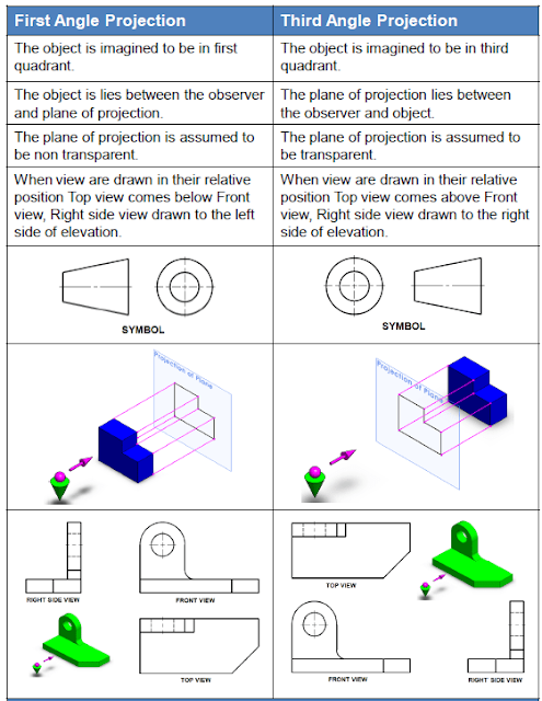
There are two types of drawing in orthographic , First Angle and Third Angle. They differ only in the position of the plan, front and side views.

First Angle Projection :

1.)In first angle projection, that object is assumed to be in the first quadrant. Hence, the top view is projected below, i.e. to the x-z plane - which lies below the object.
2.)The object is assumed to be positioned in between the projection planes and the observer.

3.)The views are obtained by projecting the images on the respective planes.
4.)First Angle Projection is commonly used in all countries other than United States. The Indian Standard Institution (ISI) recommend the use of First Angle Projection method now in all the institutions.
5.)In first angle projection right view come in left of front view and top view come at the bottom of front view.
Fig : First Angle Projection

Third Angle Projection:

1.)In the third angle projection method, the object is assumed to be in the third quadrant. i.e. vertical Plane is in front of the object and the Horizontal Plane is above the object.
2.)For the third angle projection plane of projection is placed between the object and observer.
3.)Third Angle Projection is commonly used in United States of America.
4.)In third angle projection right view come on right side of front view and top view comes at the top of front view.
Fig:Third Angle Projection

Major differences between first angle and third angle projection:


If you find this article helpful kindly share it with your friends and if you want to add something to it feel free to write in comment box.

KNOW HOW TO READ BEARING SPECIFICATION !!

A bearing is a machine element that constrains relative motion to only the desired motion, and reduces friction between moving parts.

Each bearing has a specified number which tells about the type and size of bearing.

Let's take an example below :


  • (1) Prefix :
  •   
  • (2) Basic Number:
  •   
  • (3) Suffix


    • Prefix

      KCage with roller elements
      LRemovable bearing ring
      RRing with roller set
      SRoll body of stainless steel
      WStainless steel deep groove ball bearing
      *Note: Each bearing company may create their own prefixes. e.g. E2. = SKF Energy Efficient bearings

      Suffix

      2 RSBearing with rubber seal on both sides. RS provides a better seal but more rolling friction than 2Z.
      RSBearing with rubber seal on one side, one side open.
      2 Z / ZZBearing with a metal seal on both sides.
      ZBearing with a metal seal on one side, one side open.
      EReinforced Design
      P2Highest precision
      KBearing with taper bore

      Bearing Numbers

      The example at the header shows a 6001 2RS bearing. So what does the 6001 actually mean?
      (6)001
      This first number relates to the bearing type, as shown in the table below type 6 is a deep grooved roller bearing.

    • Lets attempt to break it down.


    • 1
      Self-Aligning Ball Bearing
      This kind of ball bearing has a spherical outer race, allowing the axis of the bearing to "wander around". This is important because misalignment is one of the big causes of bearing failure.
      2
      Barrel and Spherical Roller Bearings
      3
      Tapered Roller Bearing
      Designed to take large axial loads as well as radial loads.
      4
      Deep Groove Double-Row Ball Bearing
      Designed for heavy radial loads.
      5
      Axial Deep Groove Ball Bearing
      Intended for exclusively axial loads.
      6
      Deep Groove Ball Bearing (Single row)
      Typical ball bearing. Handles light axial loads as well as radial loads.
      7
      Single-Row Angular Contact Bearing
      Specific geometry of angular contact bearing raceways and shoulders creates ball contact angles that support higher axial loads
      8
      Axial Cylindrical Roller Bearings
      Axial cylindrical roller bearings comprise axial cylindrical roller and cage assemblies and shaft and housing locating washers.
      The bearings have particularly small axial section height, have high load carrying capacity and high rigidity and can support axial forces in one direction.
6(0)01
This second number relates the bearing series, which reflects the robustness of the bearing. As you go up the scale below from 9 to 4 the inner and outer race thickness will usually increase along with the ball size, this will be to help cope with extra load.
9 Very thin section
0 Extra light
1 Extra light thrust
2 Light
3 Medium
4 Heavy

60(01)
The 3rd and 4th digits of the bearing number relate to the bore size of the bearing, numbers 00 to 03 have a designated bore size depending on the number.
00 10mm
01 12mm
02 15mm
03 17mm


While numbers over 03 simply have a bore size which is 5 times that of the 3rd and 4th digit.